Humble Beginnings in Electronics
When I was this summer at my parents, I rediscovered a long-forgotten “electronics lab box”. I was super glad, since it was that box that enabled me to get into electronics. Not the digital kind with micro-controllers, but the old-school analogic one, with transistors, resistors & capacitors.
The Electronics Lab Box
The set itself is the French version of a Philips created one. There’s actually a full collection of those.
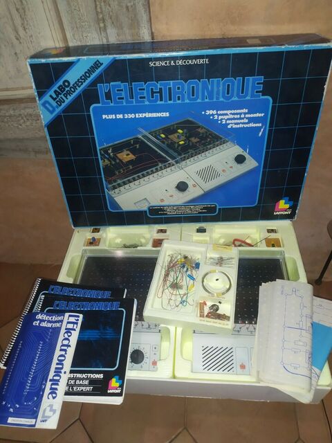
Image taken from ebay
How it worked
It was actually super clever:
- You didn’t need any soldering as there’s some spring to fasten the connections
- the circuits where therefore rather large, so a kid like me could understand how it is connected
- every sample circuit came with a blueprint paper that you could put underneath the components for super easy setup.
But the real gem was the manual next to it
- It started with some very interesting circuits that you could try out.
-
Then it went with simple explanations
- Making the real circuit & the symbolic one just next by
- Starting with the LED and a resistor.
- Then gradually becoming more complex, with a RC couple. Trying various combinations with R in series, parallel. C in series & parallel.
- Going via the transistor, saturated at first and amplifying next.
- At the end you had the IC. Which is actually an op amp.
This was a real eye opener to my son. Specially since it was written in French. As he doesn’t really understand English, therefore the usual resources on the Internet aren’t that helping.
He actually went on a regular breadboard (as I only could salvage the books from the set) and experimented there along the reading.
He actually learned the “multivibrator astable” schema by heart and tried various configurations. ;-)
Next steps - NE555
I then got my hands on a NE555, due to an electronic kit for soldering up-skilling. My son wasn’t super interested in soldering as breadboards are reusable, and he doesn’t like to “waste” some parts :D
As his breadboarding skills were now rather optimal, I could feed him with some advanced NE555 setup. We tried the traffic light one, but it wasn’t working.
We discovered that, as we only had a 5/3.3V breadboard power bar, 5V wasn’t enough to power the 2nd NE555 since there’s a fixed voltage drop and the out on pin 3 is only delivering 3.5V.
So, we had to use the pin 7 with an open-collector and convert it to a rail-to-rail (mostly) output via a couple of transistors. But that will be in another article.
