Minimal NE555 Blink
My son recreated the “blink” with a NE555 and tried to remove the wire from RESET pin to VCC. It actually worked well, and we wondered “what’s the minimal BOM for a NE555 blink ?”.
This made sense as “Blink” is the “Hello World” equivalent of electronics, and the latter is used to compare programming languages.
Rules of engagement
The rules are :
- Everything counts as a BOM item, except power. Even a wire.
- Power is coming from 2 Dupont wires : VCC & GND.
- It has to work on a breadboard.
- Only very simple to source components are allowed1.
Findings
I remembered that I saw a circuit out there that reused the OUTPUT pin (pin 3) to charge and discharge the RC timing. The duty cycle is therefore always 50%, but that’s actually perfect for Blink.
It has several shortcomings, as the number of components is not lower than the regular astable.
Improvements
The TI LMC555 datasheet has a better version of it as mentioned in an electronics.stackexchange.com answer, since it lacks the R1 that is connects TRIG to VCC.
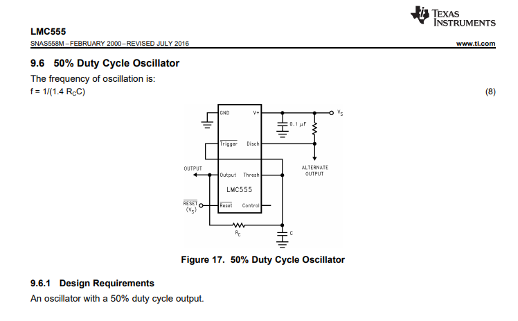
It works since the LMC555 is much more closer to have a rail-to-rail OUTPUT than the regular bipolar NE555, but as we aren’t interested in accuracy, we can also omit it with out regular NE555.
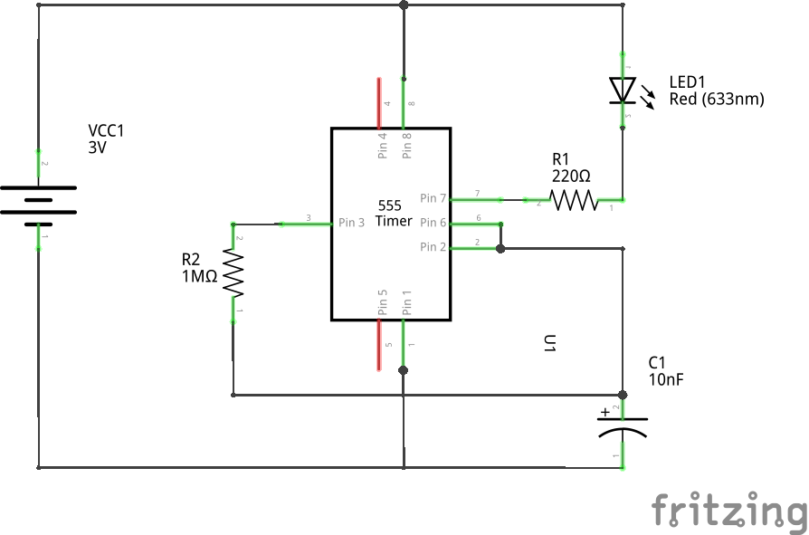
Leveraging the open-collector output
As we are not using the DISCHARGE pin anymore for timings, we can use it for output. That has an interesting properties : the timings aren’t affected by the load.
So the schema is very simple.
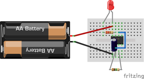
And indeed, the breadboard version is minimal.
And for real.
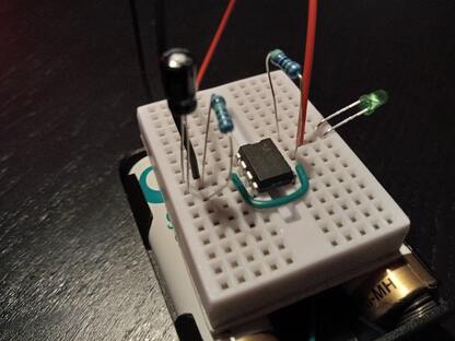
Mission accomplished!
Future Ideas
The open collector output makes me think that it can be multiplexed with other blinks. I might toy with that idea.
-
Breadboards, Wires, Resistors, capacitors, LED. ↩
