DIY 4-digit Clock Hacking
I got my hands on a 4-digit clock DIY kit. Soldering it is rather easy, and it works as advertised.
One downside is its power appetite : it slurps a whopping 100mA constantly, which means that operating it from a battery is going to be an very tedious & expensive proposition.
Upon close look, there is actually a 5V DC connector and a 3V one. The 5V is obviously for a wall socket DC adapter, and the 3V one is for a battery indeed, but only to retain the time, as it cannot power the LED, nor the alarm. I specifically didn’t want the alarm to sound, so i didn’t solder the PNP, nor the buzzer.
Quick hack to reduce the power usage
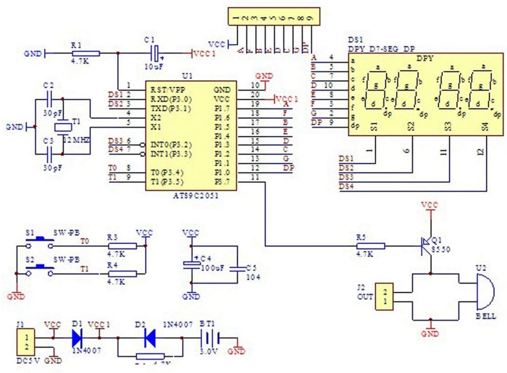
That made me think that the biggest contributor to the power is maybe the 4 digit 7 segments LED. Upon close look it shows that the 4 digits are lit in a circular fashion, but for a particular digit, the OFF state of a segment is done via pulling the IO pin low, sourcing the current via the IO pin instead of via the LED. Very simple but not very efficient.
So, I changed the pull-up 470Ω resistor array to a 10kΩ one to limit the current passing via the LED or the IO pins. This worked by immediately lowering the 100mA to 7 mA. The luminosity was rather low, but I don’t mind as this works perfectly in a dark room. As it is the purpose of that clock, and before it was too bright anyway.
That enabled a pack of 3 AA NiMH cells (2000mAh) to last a little less than a week before needing to recharge. Not bad for such a small hack.
Reprogramming
DIY Programmer
That said, I do really like that the hour-minute separator blinks, as it shows it is working, that there’s still enough battery. This requires to reprogram the MCU.
This clock is powered by the venerable and well-known AT89C2051. The annoying part is that programming it requires a HVPP1 that operates on 12V and with a parallel bus. This means that I cannot simply leverage an USBasp programmer.
As usually, the AT89 official programmer is quite expensive, and not super easy to use, so I have to come up with another alternative.
Fortunately, the AT89C2051 being very common, there’s already a lot of DIY projects that do parts of the programming. The most promising version is the AT89C2051 Programmer from Paul Gallagher.
It ticks mostly all of my needs, smashing many of the existing projects into a pretty nice feature-full version :
- On board 12V DC generation.
- Using a hardware-based 12V regulation (Zener).
- Comes with a portable CLI-based programmer on the desktop.
- Arduino UNO, less expensive than the Arduino MEGA.
Firmware dump
Fortunately the lock bits were not set, so I could dump the firmware before to do some analysis. I struggled for a while in not being able to dump the firmware via the programmer. But it turned out there’s a small timing bug. Once fixed, the dumping works flawlessly.
:100000000207DFFFFFFFFFFFFFFFFFE119D128C25B
:10001000B37F287E00F18FD2B322FFE1F6E52F7087
:100020001DE53075F00A84FFE53075F00A84E5249B
:10003000B1B0FBE52475F00A8485F00BF1A4E52F3F
(...)
:1007E0007FE4F6D8FD75813902075EFD25BBAF6752
:1007F000CFDFA5FFEF03758DFE758BCAB2B732FF51
:00000001FF
I convert it to ASM via dis51, but unfortunately it doesn’t really make sense to me.
The 2 dumps are 4digitclock.hex and 4digitclock.s
Future work
So, while the UNO programmer HAT is working nicely, I still want to be able to leverage a bare ATmega328 for it. My ideal goal would be to leverage avrdude, emulating an USPasp device.
Let’s see.
-
High Voltage Parallel Programmer ↩
