Simple AT89C2051 programmer with Arduino
Several AT89C2051 programmers exists. The most advanced one being the one from Paul Gallagher, as it is fully constrained. Even generating the 12V onboard with a charge pump.
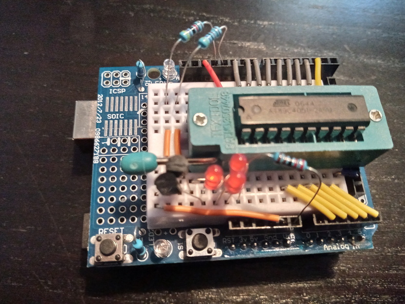
As I did want to remain on a small breadboard from the perfboard header, I didn’t have space to add the charge pump.
So, I just leveraged the fact that the Arduino Uno R3 can dynamically switch from USB powering to DC jack powering. I used a USB-12V DC/DC converter powered by an USB powerbank to generate the 12V, while still having the Arduino connected to the laptop via USB.
The 12V is then available on the VREF pin, along with GND and the 5V.
To select the RST voltage from 0, 5V & 12V I used 2 NPN transistors to pull down 12V to the required voltage. I went the cheap road to reduce 12V to 5V as I didn’t have any Zener diode handy. But 3x red LED mostly achieves the same purpose1.
The result is a very simple 0/5/12V selector circuit.

I obviously changed the RST code2. Note I also shutdown all power to every pin connected to the AT89C2051 between 2 operations. This enables hot plugging the target MCU, which is a very nice timesaver.
I also reused PIN13 (LED_BUILTIN) to power the AT89C2051 instead of connecting it to a solid 5V. As it is the first & last one to be switched on & off, it nicely shows when there is some voltage applied to the socket. I don’t expect huge current needs. The datasheet says 5mA while active at 0Hz and powered by 5V.
I finally rewired cables for a cleaner look, as we don’t need to rely on hardware PWM specific pins.